What causes a Solar fire
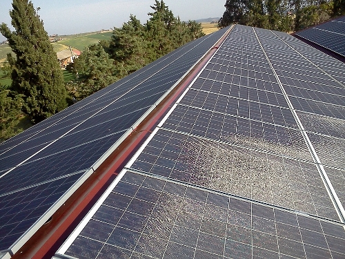
On rare occasions, a solar PV system may cause a small fire. While this is very unusual, a solar fire gets a lot of attention since solar is a relatively new technology. Consequently diagnosing a solar system to prevent solar fires is an important job for solar engineers and maintenance contractors.
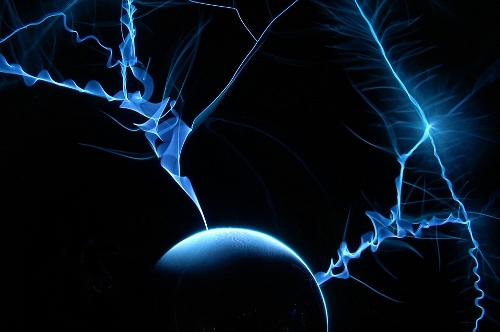
According to this report written by the BRE for the UK government, a prime suspect for a solar fire is electric arcs – the flow of electrical energy through an air gap by way of ionised gas molecules, causing the air molecules to break down into their ionised constituents (called a ‘plasma’), which provokes a large current into whatever component is nearby.


Solar fires and electric arcs
The temperature of an electric arc depends on a number of factors, such as the level of current flow, but on a typical PV system, an electric arc is easily hot enough to melt glass, copper and aluminium, and to initiate the combustion of surrounding materials.
In AC systems arcs tend to self-extinguish as the voltage alternates, passing through 0 volts 100 times per second for standard grid supplies. DC, on the other hand, remains at a continuous voltage and, once an arc has been established, it tends to keep going.
Thus any evidence of arcing found on sites, whilst not conclusive, points towards a possible, even probable, cause of a solar fire.
Causes of electic arcs
Exposure to water and oxygen can be the cause of electric arcs because they cause oxidisation of contacts, which layers onto the contacts and cause heating. This increasing amount of heat then breaks down the surrounding materials, causing a breakdown of the mechanical integrity of components, then a break in the circuit and then an arc which jumps across the break.
Poor connections can create conditions for arcs as a gap may be created between bits of the circuit.
The likely causes of electrical arcing on a PV system may be summed up as follows:
- moisture ingress degrading connections in connectors, juncion boxes and switches
- incorrectly crimped connector contacts
- the mating of incompatible plugs and sockets
- plugs and sockets not fully engaged
- loose screw termainls within junction boxes or isolators


Diagnosing solar fire risk in PV systems – insulation resistance faults
A prelimiary indicator that something is wrong in a PV system is the error messages given by the inverter. In systems where the electrical cabling is not properly connected, an inverter may give out the error message ‘insulation resistance fault’ (or something similar). An insulation resistance fault is an indication that there’s more resistance in the cables than there should be – i.e connections may be lose.
Insulation resistance faults only happen under certain conditions – when a connection is damp, for example, or when the light is low. Unless a manual electrical check happens in exactly these conditions, it’s unlikely to pick up resistance in the cabling. Consequently it’s best to perform system checks when the system is wet.
An inverter will report insulation resistance faults. But most won’t pick up in which string the IRF is happening, meaning you only know that there’s an IRF somewhere, but not exactly where in the array. You could have 120 panels attached to an inverter, and know there is a problem, but be unable to ascertain in which part of the setup the error is happening. This has been called a ‘blind spot’ in solar diagnostics – even if you know that something is happening, it’s tricky to know exactly where it’s happening.
It’s also difficult to prioritise. Most checks – manual or inverter – won’t show the severity of the problem – the amount of resistance in the string. So you won’t be able to tell the difference between a connector that’s more likely to fail than another.
And yet “investigations uncovered evidence for persistent but undetected ground faults as a condition leading to some PV fires” (see solarabcs.com)
Take a look at it actually happening. This video –
shows high current (amps) at the moment of the arc (5.10), so when the arc happens a current surge also happens. If this kind of high current appears in a solar system it could be a likely cause of a solar fire.
We have found that the best route to reduce IRFs is to get on the roof and check the MC4 connectors. While these are not the only weak spot in the cabling system (the DC isolator is another), opening MC4s and looking at the state of the cable, then replacing if necessary, has substantially reduced the amount of IRFs being given out by the inverter.
Other things you can do:
1/ look at combiner box interiors, looking for signs of water or debris buildup, heat damage on insulation, stainng of connectors and lossened string conductor connections.
2/ visual inspection of wiring, looking for pinch points, sections tightly pulled against racking etc or buildup of gunk around the wiring.
3/ checking torque on connections
4/ inspection of modles for scorch marks.